Finite Element Modeling for Wind-Exposed Structures
Finite Element Modeling for Wind-Exposed Structures
Wind-exposed structures such as light poles, site fixtures, signage, and solar-mounted systems often fall outside the assumptions implicit in simplified hand calculations. Slender geometries, eccentric attachments, and non-uniform wind pressure distributions introduce structural behavior that cannot be adequately represented using closed-form equations alone.
In these cases, Finite Element Analysis (FEA) provides a necessary framework for evaluating how wind loads are transferred through a system, how stiffness and boundary conditions influence response, and where demand truly accumulates. When applied with sound engineering judgment, FEA allows designers to move beyond approximation and toward behavior-based understanding.
1. Why FEA Matters for Wind Engineering
Simplified hand calculations often fall short when addressing the nuanced interactions of wind forces on slender or cantilevered structures. These structures may experience varying pressure distributions along their surfaces, leading to complex loading scenarios that traditional equations cannot adequately represent. Furthermore, the eccentric loading conditions, which frequently occur in real-world applications, are challenging to analyze without advanced modeling techniques. Additionally, assessing the effects of stiffness—especially when dealing with non-standard geometries—requires a more detailed approach that encompasses the entire structural system. In today's engineering landscape, where precision and reliability are paramount, FEA provides the necessary tools to ensure that every aspect of the wind's impact is considered in the design and analysis phases.
2. From Wind Pressure to Structural Response
To effectively evaluate the impact of wind loads on structures, ASCE 7 wind pressures can be converted into distributed loads for input into a finite element model. This process facilitates a comprehensive analysis of the structure's behavior by allowing engineers to evaluate stresses, deflections, base reactions, and load paths resulting from wind action. The finite element method provides a versatile framework where varying material properties and boundary conditions can be easily accommodated, enhancing the accuracy of the design. By integrating detailed simulations based on these loads, engineers not only improve the reliability of their models but can anticipate potential issues that may arise during the service life of the structure, therefore helping to mitigate risks before actual construction begins.
The reliability of finite element results depends heavily on how boundary conditions, connections, and load application are modeled. Assumptions regarding base fixity, embedment stiffness, and rotational restraint can significantly influence predicted stresses and deflections.
For wind-exposed exterior structures, inappropriate boundary assumptions can lead to either unconservative or overly pessimistic results. As such, FEA must be guided by an understanding of real-world installation conditions, construction tolerances, and soil–structure interaction rather than idealized supports alone.
3. Example Application: Site / Garden Light Structure
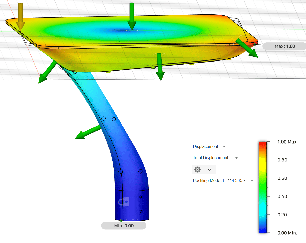
A practical example of FEA application can be seen in the analysis of a garden light structure subjected to wind loading. In this scenario, specific modeling assumptions regarding the geometry and material properties are fundamental to attaining accurate results. The boundary conditions must reflect realistic supports, while the load application mimics real-world wind forces derived from ASCE 7 guidelines. Evaluating results such as stress, displacement, and base reactions provides critical insights that inform design decisions, ensuring that the light structure can withstand the expected service conditions. This approach not only demonstrates the effectiveness of FEA but also shows how thoughtful application of these techniques leads to safer, more resilient designs in a variety of environmental conditions.
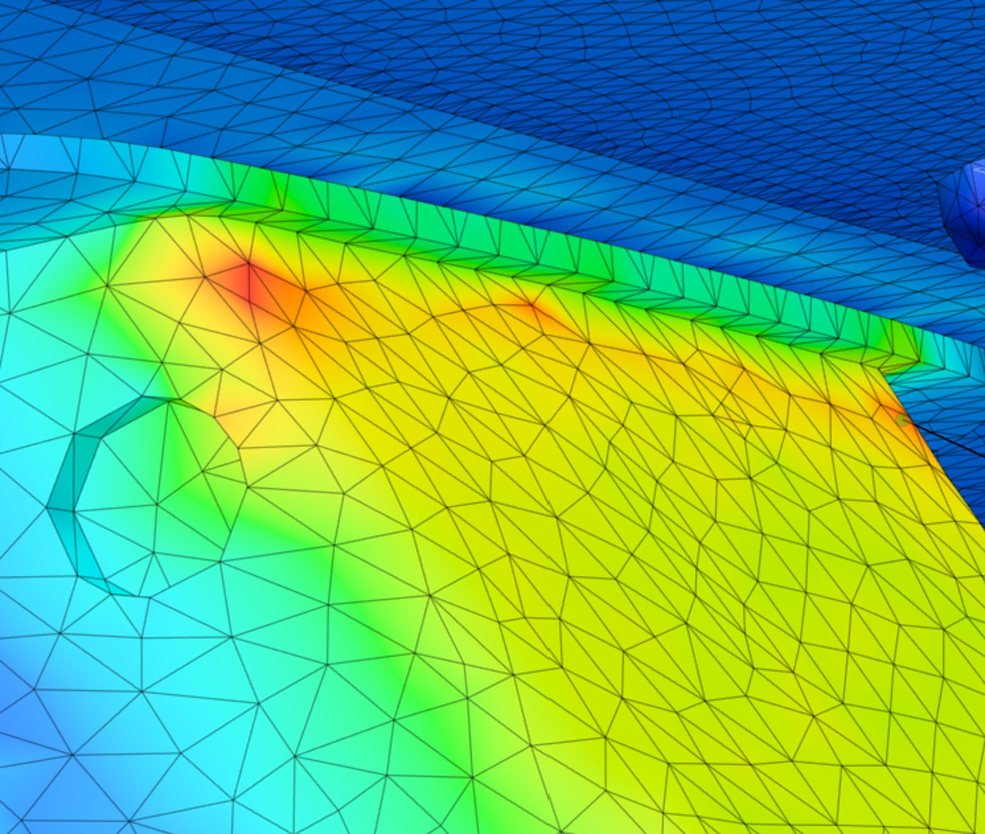
In practice, modeling of site and garden light structures often reveals that peak demand does not occur uniformly along the pole, but instead concentrates near the base transition or at connection interfaces. These localized effects can govern performance even when global strength checks appear satisfactory.
4. What FEA Reveals That Hand Calculations Cannot
Finite Element Analysis routinely reveals behavior that is not apparent from simplified calculations, including localized stress concentrations, stiffness-driven load redistribution, and connection demand that governs system performance. In many wind-exposed assemblies, failure initiates at details rather than within primary members, particularly under cyclic or dynamic loading.
5. Appropriate Use of FEA
It is important to recognize that FEA is not always necessary for every project. Its application should be selective and justified based on the complexity and criticality of the design. In many instances, simplified code-based analyses or established methodologies can be sufficient for routine applications. However, when faced with innovative designs or challenging loading conditions, FEA can provide invaluable insights that contribute meaningfully to the engineering process. This judicious approach ensures that resources are allocated effectively while still upholding the highest standards of safety and performance.
6. How This Informs WindCalculations’ Engineering Approach
By integrating ASCE 7 wind loading with FEA, engineers can enhance the reliability of design decisions. This combination not only supports the creation of defensible engineering documentation but also reduces uncertainties for permitting officials and manufacturers, fostering confidence in constructed systems. The robust analytical framework ensures that designs are not only compliant but optimized for performance. Such meticulous integration of various engineering principles aids in achieving a well-rounded perspective on not just compliance, but the potential for innovation in design solutions that push the boundaries of traditional methodologies.
7. Applications
Finite Element Analysis finds numerous applications within the field of wind engineering, particularly for light poles, garden fixtures, signage, solar mounts, canopies, architectural features, and custom exterior equipment supports. Each of these applications benefits from a detailed understanding of load paths and structural behavior under wind-induced forces. The versatility of FEA permits its application across various structures and scenarios, enhancing the ability of engineers to design safer and more efficient systems tailored to the specific demands of the environment.
While software and automation are valuable tools, they do not replace engineering judgment. Finite Element Analysis is most effective when used selectively, with a clear understanding of its limitations and assumptions.
At WindCalculations, FEA is applied not as a default, but as a decision-support tool—used to clarify behavior, reduce uncertainty, and inform sound engineering conclusions for wind-exposed structures.
WindCalculations.com
+1 (813) 694-8989
info@oasisengineering.com
© 2023 Oasis Engineering LLC. All rights reserved. Doing business as WindCalculations.com