150+ MPH Hurricane Testing
What Wind Really Does to Solar & Light Pole Systems
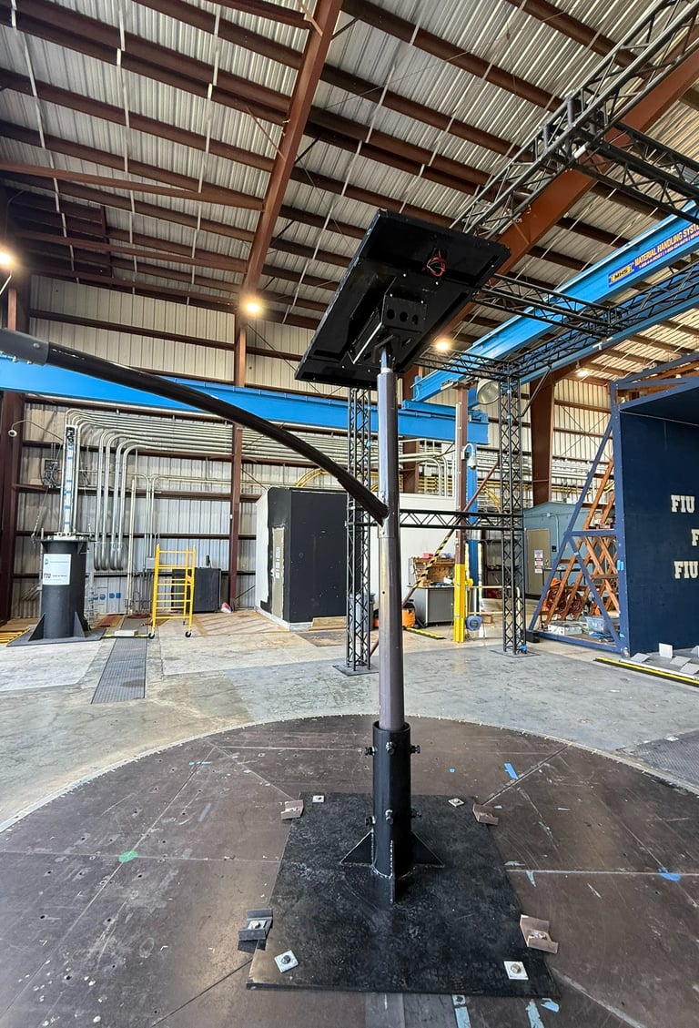
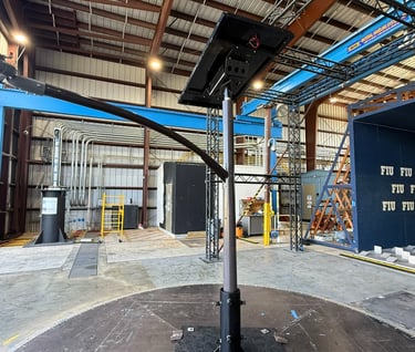
System Tested: Solar Fixture / Light Pole Assembly
The tested system consisted of a solar-powered lighting fixture mounted to a vertical pole structure intended for exterior, exposed environments.
Key characteristics observed during testing:
Slender vertical pole geometry
Elevated center of pressure
Cantilevered mounting condition for light fixture arm
Exposure consistent with open terrain conditions
Connections representative of typical field installations
From a design standpoint, the system was expected to:
Experience increasing lateral deflection with wind speed
Remain elastic within anticipated service-level winds
Transfer loads primarily through base anchorage and connection hardware
The test environment allowed these expectations to be evaluated directly.
Most wind engineering relies on analytical models, code-prescribed coefficients, and conservative assumptions derived from historical data. While these methods form the backbone of ASCE 7 and the Florida Building Code, they are ultimately representations of real behavior — not direct observation.
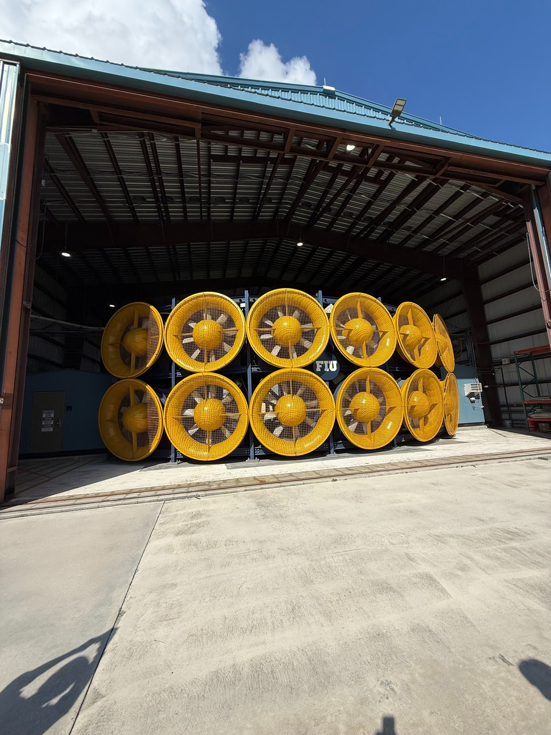
At Florida International University’s Wall of Wind (WoW) facility, full-scale structures are subjected to simulated Category 4–5 hurricane wind fields, with wind speeds exceeding 150 mph. Unlike wind tunnel testing or component-level lab tests, the Wall of Wind allows engineers to observe how entire systems behave under sustained, turbulent, real-world wind loading.
WindCalculations participated in on-site testing of an exterior solar fixture / light pole system, observing structural response under extreme wind conditions that exceed typical design events.
This experience provided rare, applied insight into how wind loads are actually transferred through real structures — beyond what equations alone can show.
Observed Behavior Under Extreme Wind Loading
As wind speeds increased into hurricane-level ranges, several important system-level behaviors became clearly visible. These observations highlight the difference between structural capacity, dynamic response, and component vulnerability under extreme wind demands.
1. Dynamic Movement and System Interaction
At elevated wind speeds, the system exhibited significant dynamic behavior. The cantilevered arm and the solar fixture mounted at its end were observed to move in phase, with the arm and solar panel responding together as a coupled system.
This synchronized motion was notable, as it demonstrated that the behavior of the assembly was governed not by isolated component stiffness, but by the combined flexibility and mass distribution of the arm, mounting hardware, and solar fixture. As wind speeds increased, motion became increasingly dynamic rather than static, emphasizing the role of stiffness and damping in overall performance.
2. Deflection Without Immediate Structural Failure
Moderate to significant visible deflections were observed prior to any signs of global structural failure. Despite the noticeable movement, the primary support assembly remained intact through wind speeds approaching the certified design range.
This behavior reinforced an important distinction between serviceability response and ultimate strength. While the system exhibited visible movement that could be perceived as alarming, deflection alone did not immediately indicate loss of load-carrying capacity or imminent collapse.
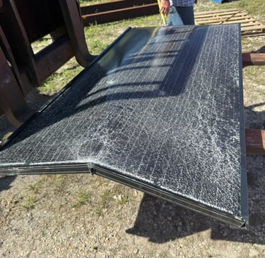
3. Component-Level Failure at the Solar Panel
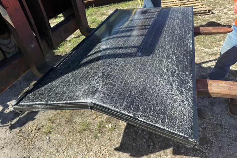
At wind speeds on the order of approximately 150–153 mph, distress did not initiate in the primary support arm or base connection. Instead, failure was observed at the solar panel assembly itself.
The solar panel, consisting primarily of glass and polymer-based materials, proved to be the most vulnerable component in the system. As the panel moved upward and downward under dynamic wind loading, localized interaction with the support bolts created stress concentration points. These localized demands are believed to have initiated cracking within the panel, ultimately leading to fracture and upward bending of the panel assembly.
Importantly, this failure mode was component-controlled, not a global structural failure of the support system.
4. Implications for Load Paths and Assumptions
The observed behavior demonstrated that real-world load paths under extreme wind can differ meaningfully from simplified assumptions. While the structural support assembly had been engineered and certified to withstand wind speeds on the order of 150 mph, the performance of the system was ultimately governed by the weakest interacting component — in this case, the solar panel itself.
This underscores a critical lesson in wind engineering:
A system may satisfy structural strength requirements, yet still experience functional or component-level failure if secondary elements are not evaluated with equal rigor.
These behaviors are difficult to infer from calculations alone and represent one of the primary values of full-scale hurricane testing.
Boundary Conditions and Test Configuration Considerations
The test configuration utilized a fixed, rigid base connection for the light pole assembly. This boundary condition differs from many typical field installations, where similar poles are often directly embedded in soil.
Direct-buried installations generally introduce additional system flexibility and inherent damping due to soil–structure interaction. In contrast, a rigid base condition limits rotational freedom at the base, which can increase transmitted forces, amplify dynamic response, and reduce energy dissipation during cyclic wind loading.
As a result, the fixed-base configuration used during testing represents a conservative boundary condition relative to many real-world installations. Observed dynamic behavior, connection demands, and component-level distress should therefore be interpreted in the context of this more rigid support condition.
This distinction underscores the importance of considering actual field boundary conditions when evaluating wind-induced response and reinforces the need for engineering judgment beyond simplified assumptions.
Engineering Takeaways
Direct observation under full-scale hurricane wind loading reinforced several important lessons that are directly applicable to real-world wind engineering and exterior system design.
Where Code-Based Design Is Conservative
Code-based wind design procedures generally provide conservative estimates for the global structural capacity of primary members.
Ultimate strength of primary structural members is often conservatively estimated.
Global stability and overturning assumptions typically err on the safe side.
Full structural collapse of the primary support assembly is rarely the first failure mode under extreme wind loading.
In the observed testing, the primary support assembly remained intact through wind speeds approaching the certified design range, despite significant visible movement.
Where Code-Based Design Can Be Optimistic
While global strength may be conservative, several aspects of real-world behavior are difficult to capture analytically.
Connection behavior is frequently idealized in design calculations.
Dynamic effects, including vibration and cyclic motion, are difficult to quantify using static or quasi-static methods.
Local stiffness variations, installation tolerances, and interaction between components can meaningfully influence performance.
In this case, distress initiated not in the primary structural members, but in a secondary component that was not governing under traditional strength-based checks.
Component Vulnerability Can Govern System Performance
A key observation from testing was that system performance was ultimately governed by the solar panel itself, rather than the supporting structure.
Although the support assembly had been engineered and certified to withstand wind speeds on the order of 150 mph, the solar panel — composed primarily of glass and polymer-based materials — proved to be the most vulnerable element. Dynamic upward and downward movement of the panel led to localized stress concentrations at bolt locations, which are believed to have initiated cracking and subsequent panel fracture and upward bending.
This behavior highlights an important distinction:
A structure may satisfy structural wind load requirements, yet still experience component-level failure if interacting elements are not evaluated with equal rigor.
Why Stiffness and Mounting Matter More Than Strength Alone
Increasing member strength without addressing the following often yields limited improvement in real-world performance:
Connection detailing
Anchorage stiffness
Embedment conditions
Overall system flexibility and damping
In practice, how a system is mounted and restrained frequently governs dynamic response and component demand more than the nominal strength of the primary member.
How This Informs WindCalculations
WindCalculations’ engineering approach is informed not only by code compliance, but by observed structural behavior under extreme wind conditions.
This experience directly influences how we:
Interpret force coefficients and exposure assumptions
Evaluate mounting configurations and load paths
Identify critical component interactions
Communicate limitations and risks clearly to clients and authorities having jurisdiction
Rather than relying solely on minimum code compliance, our assessments reflect an understanding of how systems actually behave when subjected to hurricane-level wind demands.
The result is:
More defensible engineering letters
Cleaner, clearer submittals
Fewer reviewer questions
Better alignment between design intent and field performance
Validated by Full-Scale Hurricane Testing
WindCalculations’ methodologies are informed not only by ASCE 7-22 and FBC 2023, but also by direct observation of full-scale structural behavior under simulated hurricane wind speeds exceeding 150 mph at Florida International University’s Wall of Wind facility.
This applied exposure allows our engineering assessments to reflect how systems actually behave — not just how equations assume they do.
Most laboratories stop at data.
Most calculations stop at compliance.
WindCalculations connects:
Testing
Analysis
Judgment
This perspective is particularly valuable for:
Solar racking systems
Light poles and site fixtures
Signage and equipment supports
Canopies and shade structures
Exposed exterior components in coastal and hurricane-prone regions
Designing for hurricanes isn’t theoretical. We’ve seen what survives.
Development Status and Product Information
The system shown in this testing represents a development-stage product undergoing evaluation and refinement. The configuration observed during testing does not reflect a final commercial design.
The product is subject to ongoing development, including proprietary design enhancements and reinforcement strategies, and may be covered by pending intellectual property protections. Observations documented herein are intended to illustrate system-level behavior under extreme wind loading and should not be interpreted as final product performance.

Engineering Analysis of This Test
This video documents component-level failure observed during full-scale hurricane wind testing at FIU’s Wall of Wind. A detailed engineering breakdown of the system behavior, failure mode, and design implications is provided above.
WindCalculations.com
+1 (813) 694-8989
info@oasisengineering.com
© 2023 Oasis Engineering LLC. All rights reserved. Doing business as WindCalculations.com